KAMAKAZEE
Full Member
 RIDE HARD RIDE FREE
Posts: 196
|
Post by KAMAKAZEE on Sept 17, 2012 4:42:16 GMT -5
I am currently building a Yamaha XS650 chopper. All the frame fabrications, seat base and forward controls are being done by the Chopper Shed down at Willunga near Adelaide in the state of South Australia, Australia. The Chopper Shed www.thechoppershed.com/Choppers Australia Forum www.choppersaustralia.com/forum/That should all be done by the end of November then it comes back to me to be painted and assembled This is how this 1981 Model started out when I bought it for $300 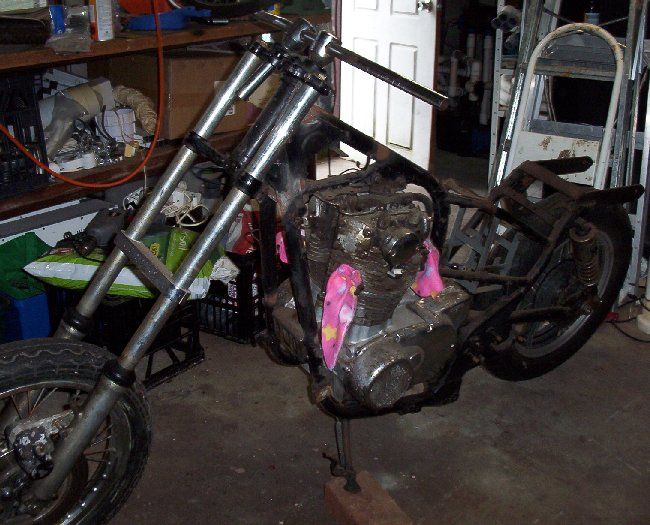 As you can see somebody that had no idea what they were doing tried to modify the frame. |
|
KAMAKAZEE
Full Member
RIDE HARD RIDE FREE
Posts: 196
|
Post by KAMAKAZEE on Sept 17, 2012 8:53:04 GMT -5
The following text is by Andrew the dude that is doing the frame modifications. KAMAKAZEE sent down his xs frame to be chopped. He included his 8" over forks and a set of tapered roller bearings and a few other bits including mudguard he plans to use. Up on the jig ready for action... 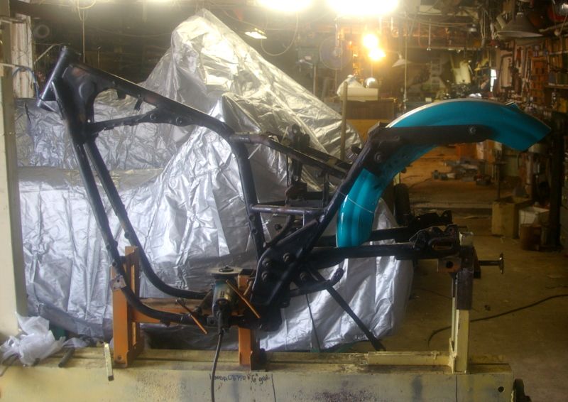 We get into the action with the angle grinders and started removing unnecessary metal work... 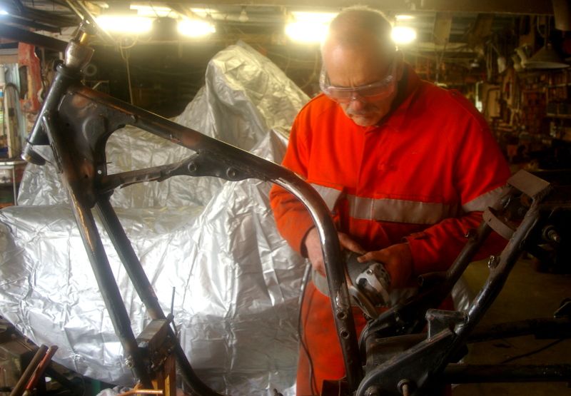 Backbone heated at the bend and headstem is pulled up about 4". Then we put in the triple trees forks and a front wheel so the rake can be set up to allow the chopper to sit level with 4.5" ground clearance. When doing this we need to allow some estra height to allow for about 3/4" drop once the bike is complete and resting on the springs. 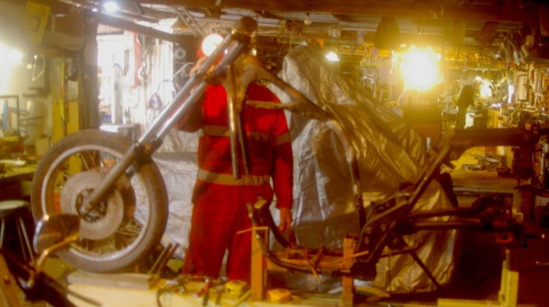 |
|
KAMAKAZEE
Full Member
RIDE HARD RIDE FREE
Posts: 196
|
Post by KAMAKAZEE on Sept 17, 2012 8:58:11 GMT -5
A phone call to clarify tank to be used (sporty) and tunnel depth and we decide to clear away all the gusseting and extra tubing to clean up the headstem area. We will replace all this ugly metal work with something tidy and flowing... 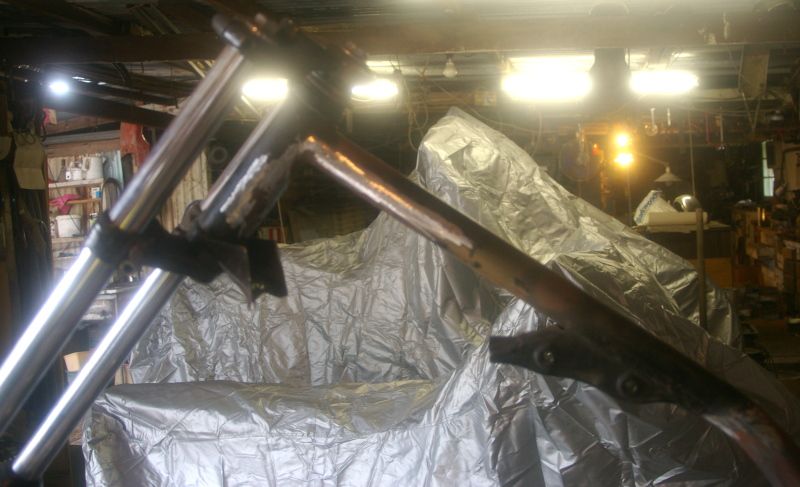 We'll put in two completely new down 28mm tubes to match the bottom tube. A couple of slugs are turned up to join things down at the engine mounts. They are chamfered one the bottom end as the frame tube on the bike is flattened and out of round and they will need to be hammered in with heat. 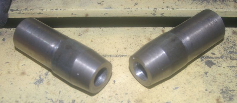 Each bottom tube has been heated to cherry red and the slugs hammered in... tight and round... 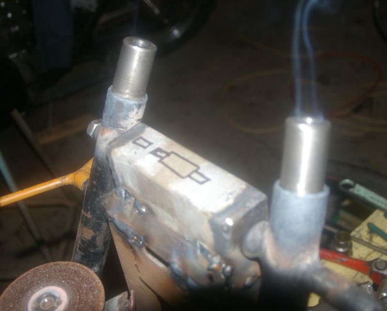 |
|
KAMAKAZEE
Full Member
RIDE HARD RIDE FREE
Posts: 196
|
Post by KAMAKAZEE on Sept 17, 2012 9:02:12 GMT -5
A pair of down tubes are bent up (28mm x 2mm wall) and cut to rough length and set in. Much tidier. 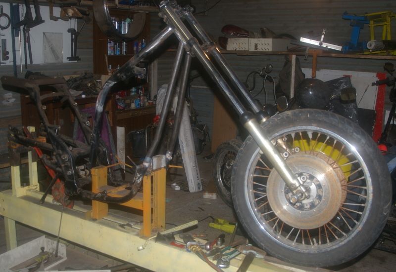 Rake ends up at 43 degrees and axle to head stem centre distance is 590mm (40mm over the regs), but I was told not to be too worried about that. Once the seat rails are lowered and the seating position moved back about 4" with the high head stem this is going to be one nice cruising chopper! The rider will be nicely tucked down into the machine especially as the riders height is only 5'2"... one reason we are going low with the seating. Next job will be to do the final shaping of the down tubes where they meet the steering head. Then we'll remove the front end and set up the laser and plumb line to get every thing spot on. After that we'll get into the back end and completely rebuild it from the centre post back... with a couple of twists that will be just the ticket. |
|
KAMAKAZEE
Full Member
RIDE HARD RIDE FREE
Posts: 196
|
Post by KAMAKAZEE on Sept 17, 2012 9:11:25 GMT -5
After taking up the mornign with phone calls, emails and ordering, we are back onto the xs this afternoon... Downtubes were cut and bent last night.. 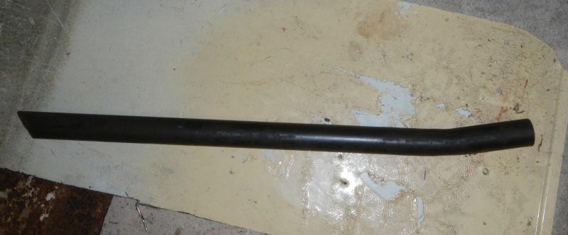 Now being shaped for final fitting here getting bottom ends squared on linishing machine... 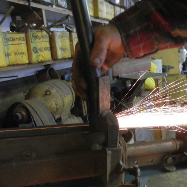 Drilled ready for plug welding... 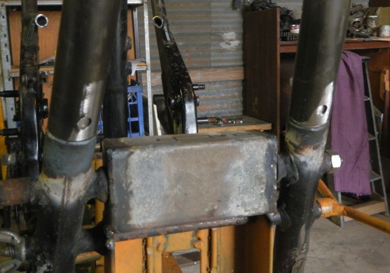 |
|
KAMAKAZEE
Full Member
RIDE HARD RIDE FREE
Posts: 196
|
Post by KAMAKAZEE on Sept 17, 2012 9:18:20 GMT -5
Takes time to get a close fit on the back of the head stem... many trips between frame and grinder! 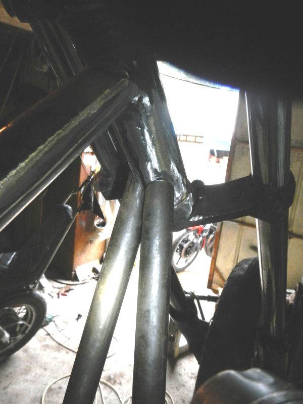 Meanwhile... armed with a recipro saw and this is what we got up to! Good thing we didn't need that bit!!! Not much left of the original frame now... 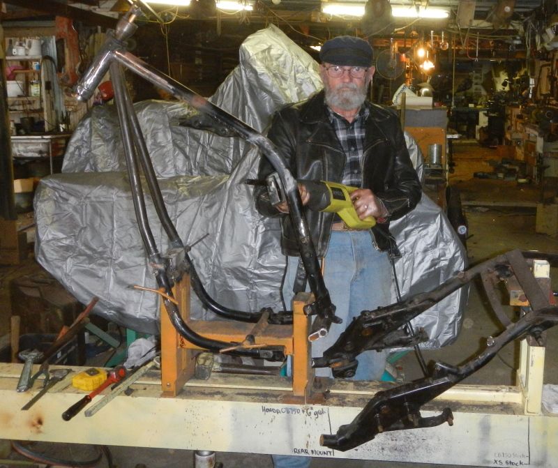 Final check on fit and correct rake... 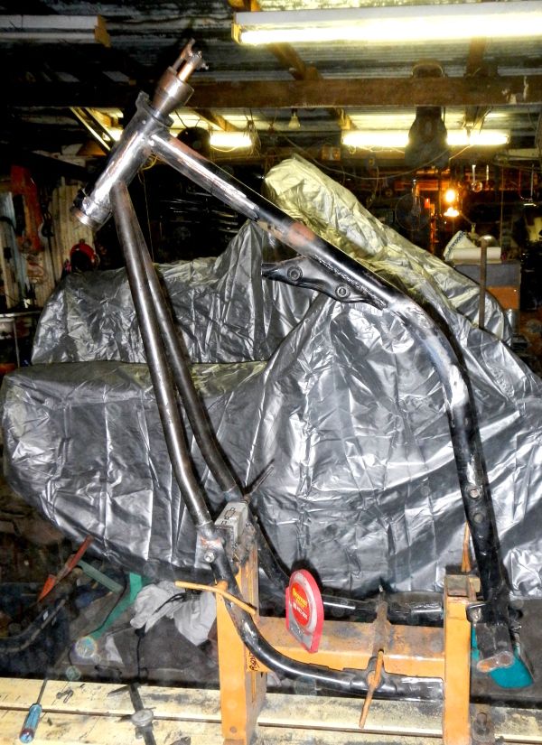 |
|
KAMAKAZEE
Full Member
RIDE HARD RIDE FREE
Posts: 196
|
Post by KAMAKAZEE on Sept 17, 2012 9:21:38 GMT -5
Now to get it all lined up... apply heat and twist with a big stillson so that... 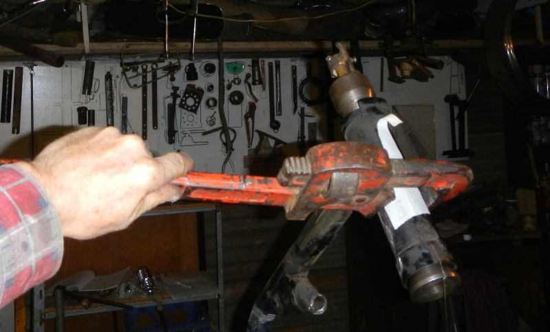 Steering head is centred... 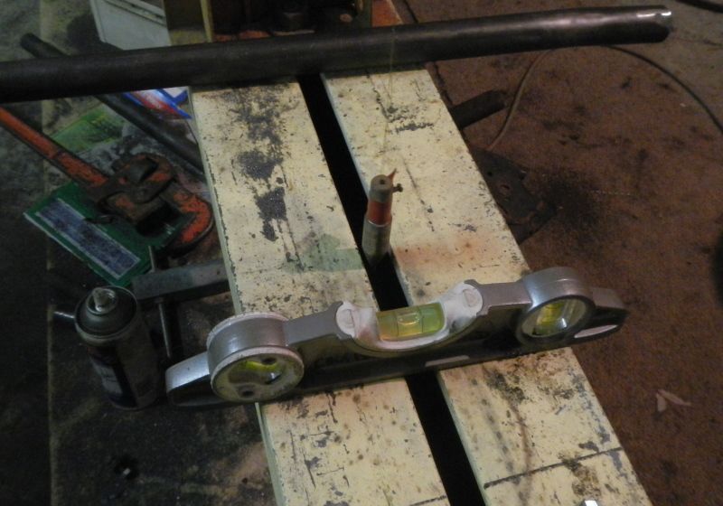 ... and aligned... laser shows it is spot on. It will move around a bit as we weld and will need checking... 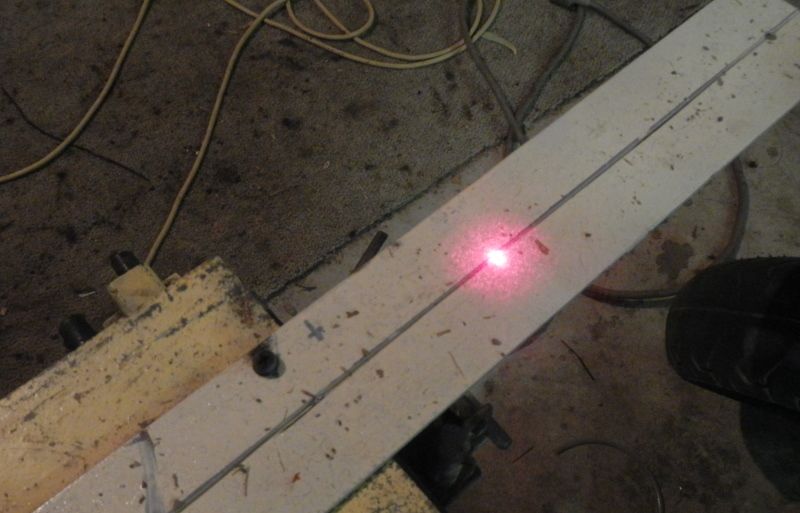 |
|
KAMAKAZEE
Full Member
RIDE HARD RIDE FREE
Posts: 196
|
Post by KAMAKAZEE on Sept 17, 2012 9:24:58 GMT -5
This fillet has been measured off a carboard template. It fits between the downtubes under the head stem. Always work off a centre line. A used cutting blade gives a nice curve, here being marked with my knife. 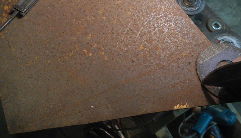 A second short tube will run similar to the stock frame, but curves down to near the bottom of the fillet. The slug will lock it to the fillet... 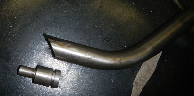 Lined up and bronze welded... a bit tricky to align so used bronze as it could be softened with heat for minor adjustments... 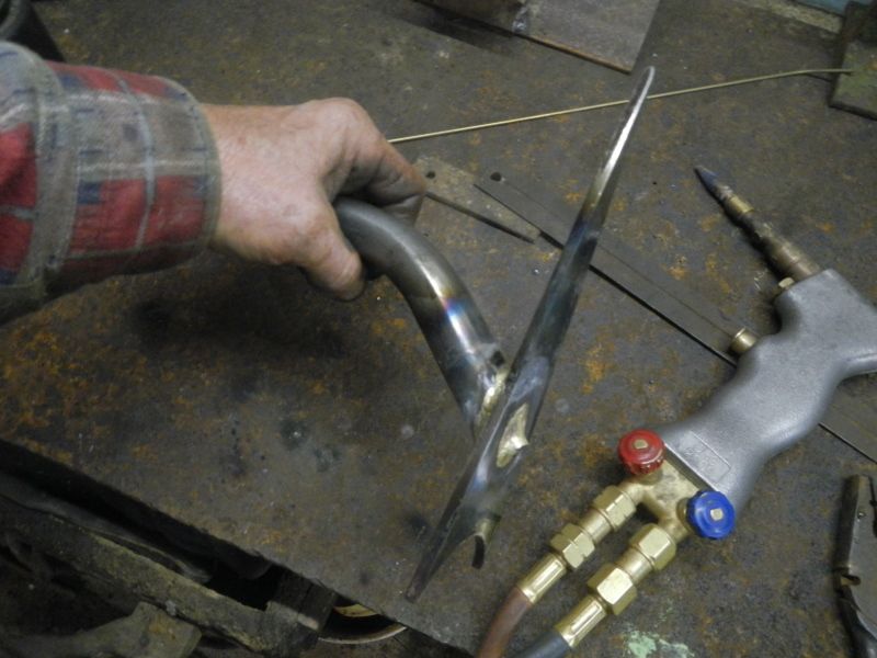 |
|
KAMAKAZEE
Full Member
RIDE HARD RIDE FREE
Posts: 196
|
Post by KAMAKAZEE on Sept 17, 2012 9:28:05 GMT -5
Fillet and secondary tube tacked in place... 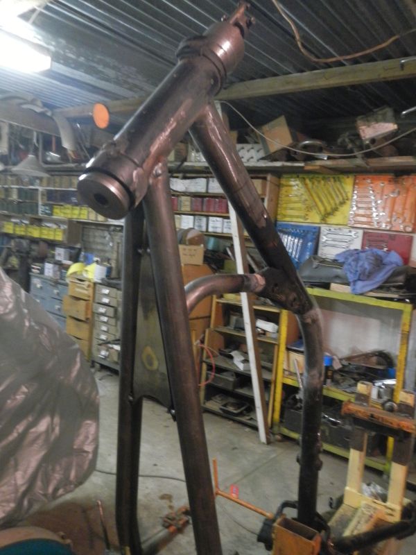 Here's another shot that includes a cardboard pattern of a planned gusset linking all components of steering head area... 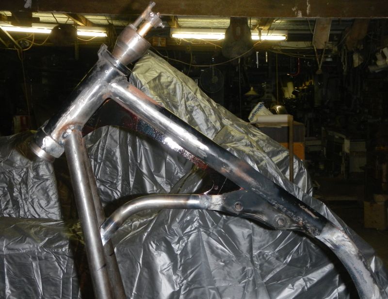 |
|
KAMAKAZEE
Full Member
RIDE HARD RIDE FREE
Posts: 196
|
Post by KAMAKAZEE on Sept 17, 2012 9:57:22 GMT -5
We are keeping the swing arm, but instead of lengthening it, we are going to move the pivot back 3". This will involve rebuilding the rear sub frame because he also wants the frame rails to flow up and around the rear wheel and also get rid of that ugly stock conglomeration of tubing and steel slabs. We are also aiming to get the seat rails nice and low. Before we went mad with the recipro saw I managed to make some register marks and measurements so we could set up the new position of the swing arm pivot... 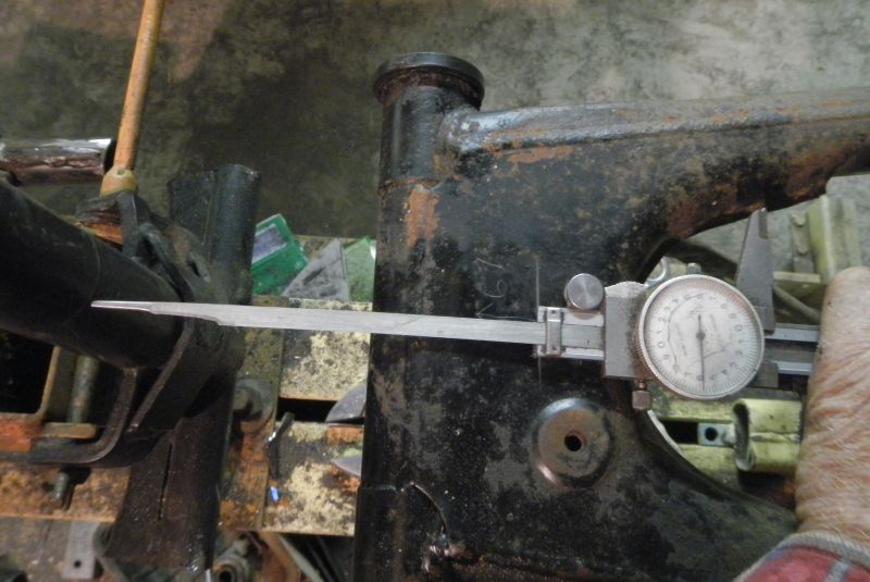 Here's the new position of the swing arm, 3" back. Now to build a subf rame... Hmm just go around to the corner chopper supermarket with my trolley and get one a la Orange County!! 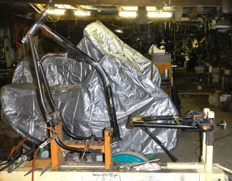 With the swing arm set up we can now get on with the rest of the rear subframe. Note that a lot of measuring is done to keep everything square. rails parallel and the same height. It doesn't take much to end up with a cockeyed frame. When measuring work from points known to be horizontal, vertical or centred. I am building the new frame sections using heavy walled 29mm tube... A couple of hollow slugs are made and installed and welded into bottom frame tube... 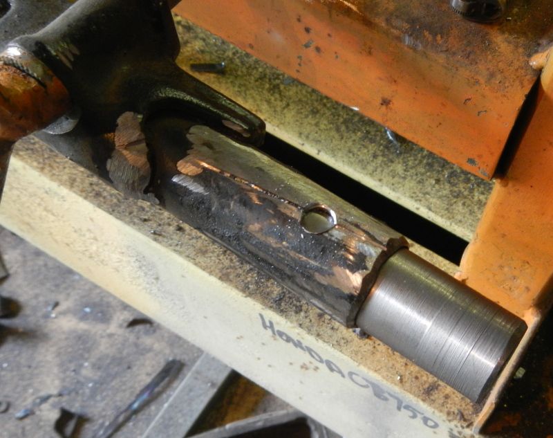 |
|
KAMAKAZEE
Full Member
RIDE HARD RIDE FREE
Posts: 196
|
Post by KAMAKAZEE on Sept 17, 2012 10:05:51 GMT -5
A length of tube is now used along with heat to bend up the short length of bottom rail... gives us almost two extra inches of ground clearance to stock, by eliminating the stock section with its large centre stand bracketry... 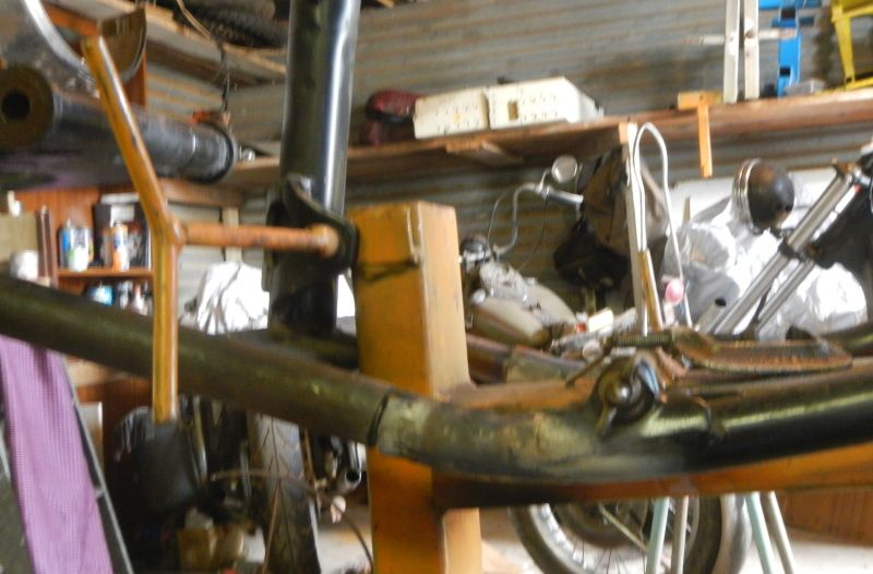 Now to set up the rear guard. A thin frame work clips onto the jig to simulate the top half of the rear wheel. A three and a half inch block is put on top of that to allow form 3" of suspension travel and the guard is set on top of that... 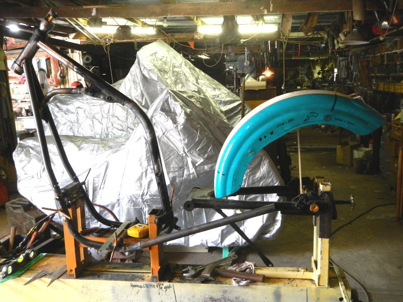 Tubing for side rails now can be measured and bent. KAMAKAZEE wants them to follow the curve of the rear guard. Yesterday I went out to a engineer friend's workshop as he has just obtained a S/H tube roller. I have priced the parts to make my own, but he thinks this one can be got up and running fairly quickly. It's not the case however, so its back to my workshop to do it the old way... lots of heat!!!! Here you can see one bent tube on on a former I have knocked up from some plate and flat bar (No charge for former KAMAKAZEE as I will no doubt use it again some time!) 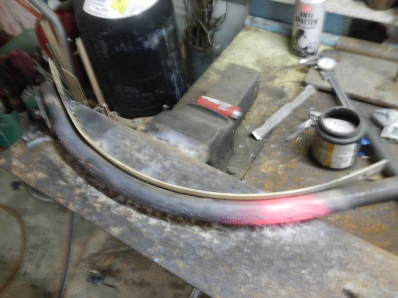 It takes a bit of time to get the two sides matching (Which is why I will be making a roller asap)... 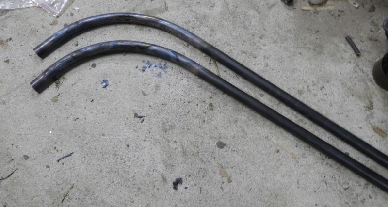 |
|
KAMAKAZEE
Full Member
RIDE HARD RIDE FREE
Posts: 196
|
Post by KAMAKAZEE on Sept 17, 2012 10:11:29 GMT -5
Then more comtemplating and measuring and an appropriate bend using my tube bender and we have a rear subframe side rail... 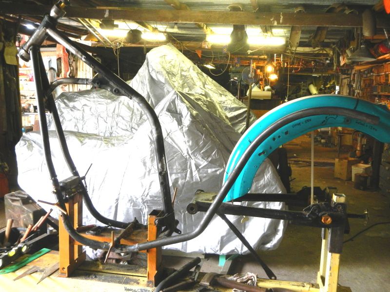 You can just see the string line I have run to mark centre, so the two side rails can be set up for tack welding at the bottom cross piece... 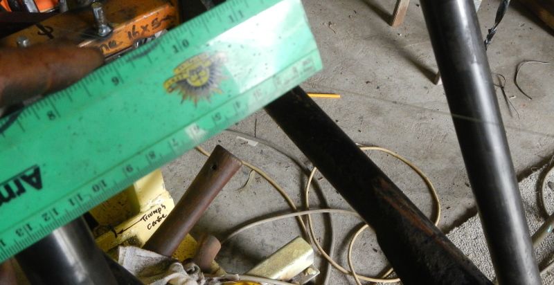 Blocks shaped and ready for welding... 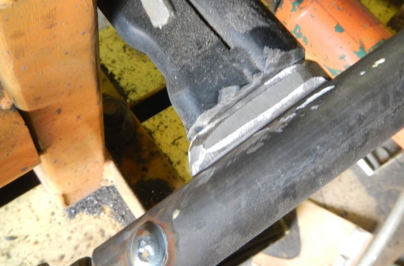 |
|
KAMAKAZEE
Full Member
RIDE HARD RIDE FREE
Posts: 196
|
Post by KAMAKAZEE on Sept 17, 2012 10:14:33 GMT -5
Now for the seat rails. First step is measuring off swing arm to keep them level at the back... 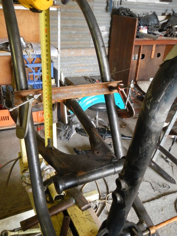 After a lot of work on the grinder the first seat rail has been made and fitted into the other tubing and tack welded. Horizontal bar is levelled and used to keep the second seat rail level... 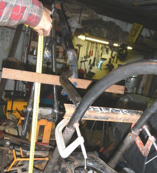 Tack welding in the second seat rail. Wide flat block of wood is used to keep any twist out of the seat rails. It is necessary because they have a bend in them which you cannot get even by eye... 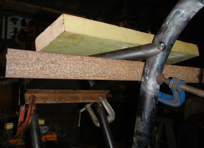 |
|
KAMAKAZEE
Full Member
RIDE HARD RIDE FREE
Posts: 196
|
Post by KAMAKAZEE on Sept 17, 2012 10:22:02 GMT -5
Seat rails tacked in place. Next step will be to tie them together where they meet the side rails. I will use a piece of wide rectangular tube that will also be a support for the rear guard... and then a triangular gusset where they meet the backbone. Seat height will be around 25". 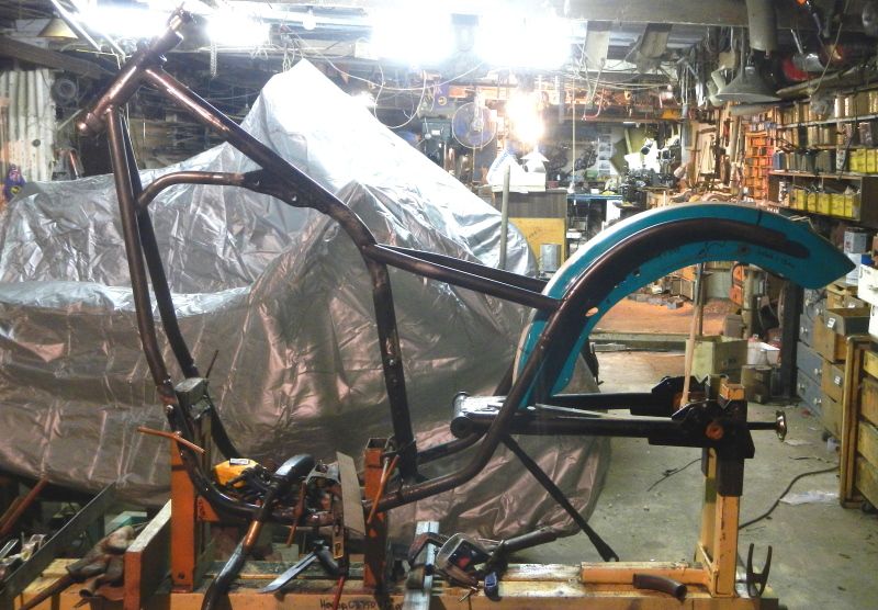 |
|
KAMAKAZEE
Full Member
RIDE HARD RIDE FREE
Posts: 196
|
Post by KAMAKAZEE on Sept 17, 2012 10:38:56 GMT -5
we're working on the rear guard mount and a gusset at the front of the seat rails. First to check with KAMAKAZEE how he wants the rear guard placed... this? Answer No... 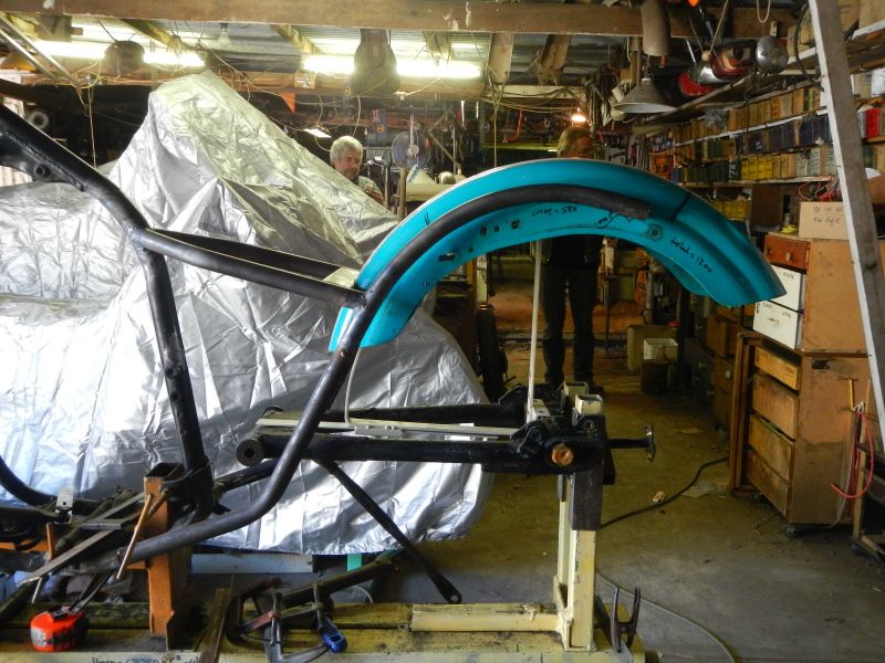 This then? Answer yes...So on with the build 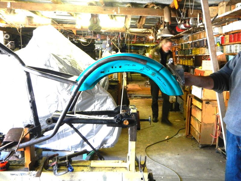 Front mount for rear guard (and bridge to lock seat rails) is next... Marking a piece of semi rectangular tube with the profile of the guard... 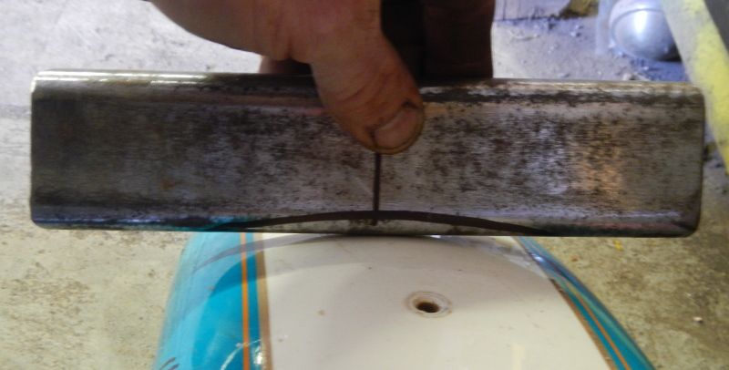 Cutting with worn out cutting discs... very handy for going around curves... always keep a few in your collection... 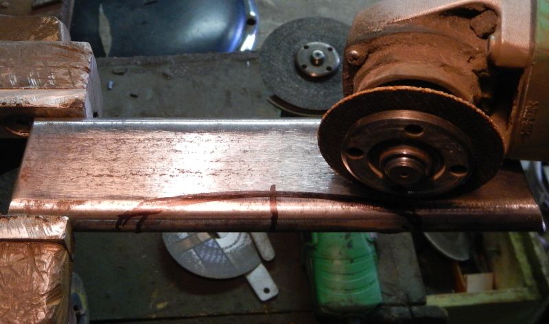 A piece of 25 x 6mm flat bar is curved in the vice (I've shown how to do this in other posts. Here it has been drilled and tapped for M8 x 1.25 and is being used to mark the guard for holes. I always make holes in guards and taillight mounts at least tw sizes large than the bolts to be used, so the items can be easily aligned before tightening. 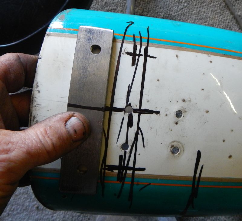 Easist way to stop drill bit wandering is to punch the metal. Stand a block of wood in the vice and hammer on that. Do the same when dirlling in a drill press.. 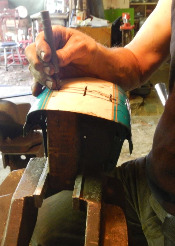 Curved bar is welded into the cross piece and then welded into the frame... 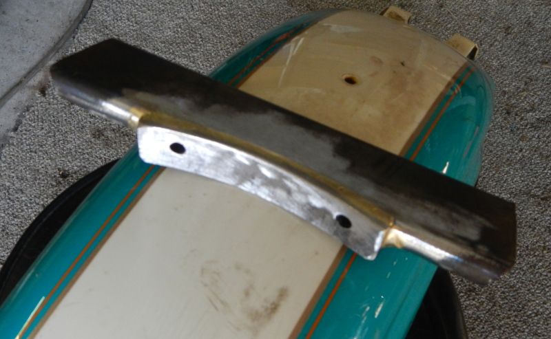 |
|